|
|
AK GenIII Cobra
|
|
|
|
AK GenIII Cobra
|
|
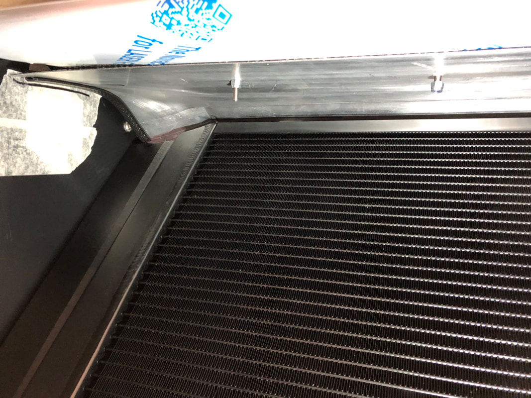
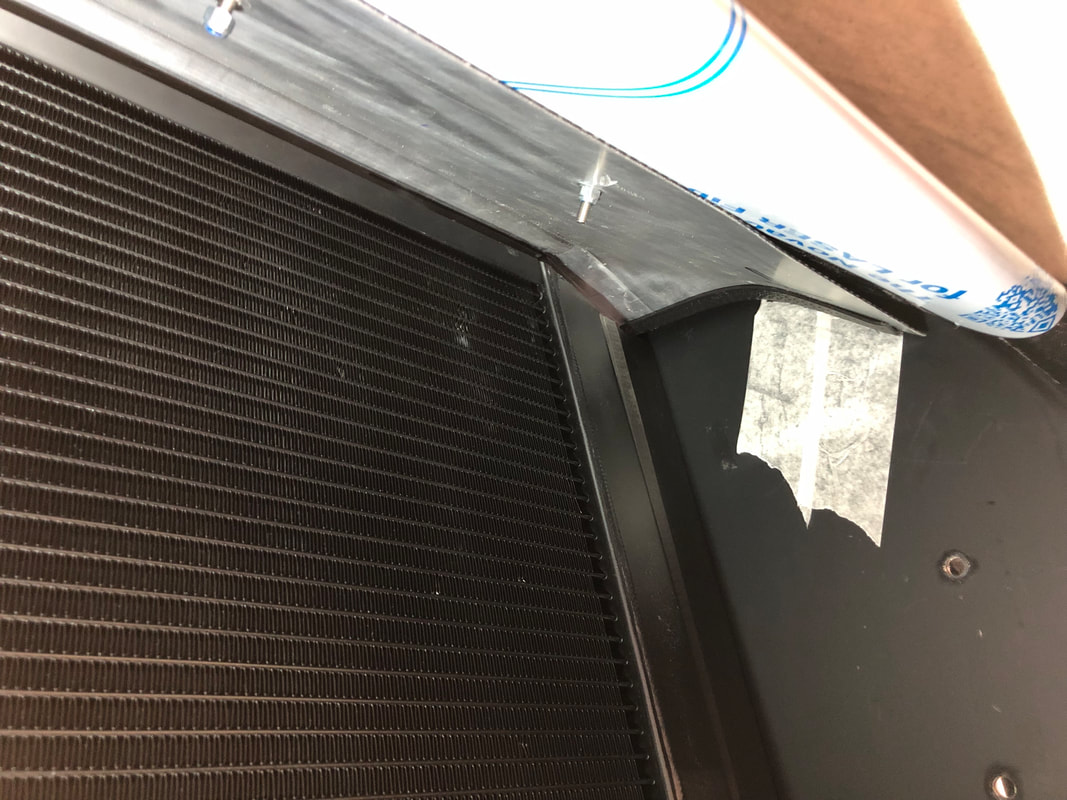
Front SpoilerI wanted to get some cold fresh air into the engine bay, but personally I am not keen on the three air intakes at the front of the car that some Cobra's have. Additionally, I would like to stop the air escaping over the top of the radiator and force it through the radiator instead. My solution was to make a splitter that would sit in front of the radiator and split the air into two. By mounting the splitter to the top of the radiator, the air that passes over the splitter can freely flow over the top of the radiator into the engine bay. While the air below the splitter is forced to go through the radiator. My original design was made of aluminium and was fixed by the two screws that hold the radiator in the top bracket. However, when fitting the body on the chassis, I found that it fouled and I had to remove it. As a revised design, I decided to cut it down and reshape the corners to follow the contours of the body (see pictures). However, the redesign reduced the length of the splitter and therefor the effectiveness. To compensate, I decided to use the single stainless steel splitter as provided by AK Sportscars to add it to what remained of my original design and extend it to its original length.
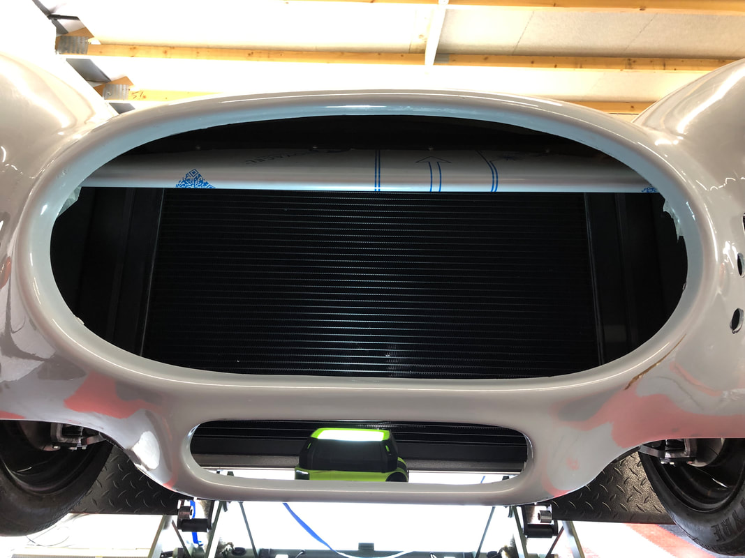 As I personally do not like the 'blingy' stainless steel inside the front of the car, I wrapped it in matt black vinyl. This gives it a stealthy look and could be removed in the future if I wanted to change the look of the car. 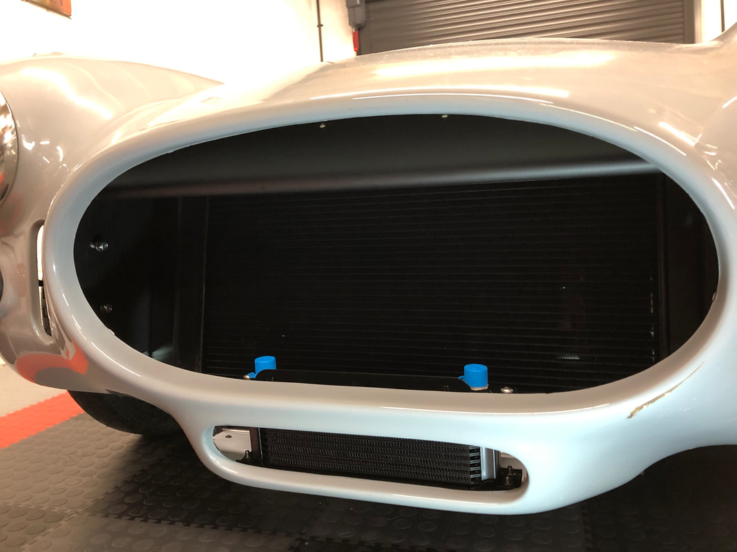
0 Comments
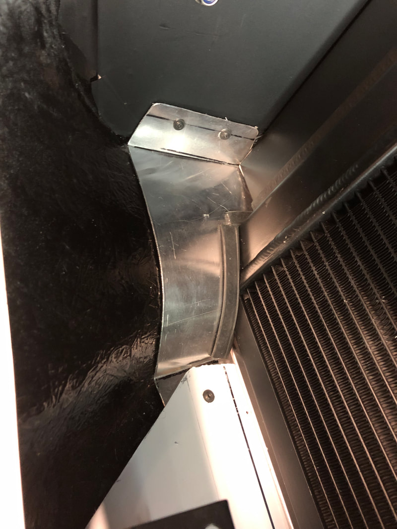
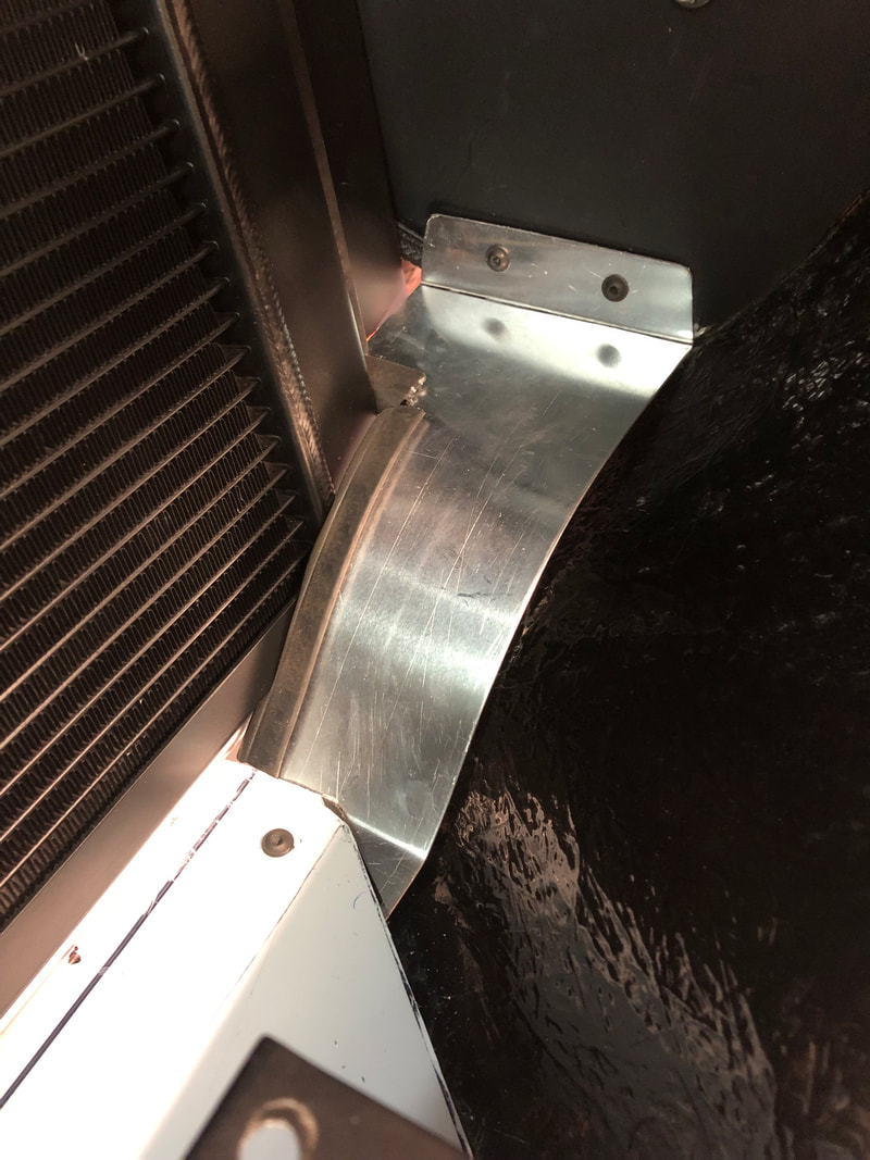
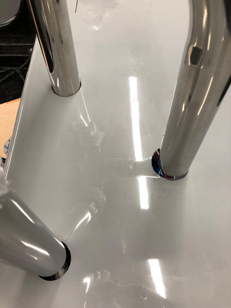
Bottom Radiator Blanking platesAs mentioned earlier in my blog, my plan is to block all gaps around the radiator to force the air through the radiator which should aid cooling performance. I already made blanking plates either side of the radiator, but I had to wait until the body was fitted on the chassis to make the lower blanking plates to fill the gap between the front of the car and the radiator. Due to the complex shape it was difficult to make it out of a single piece, so I ended up using 2mm aluminium plate for the bottom section which will also for the mounting base for the oil cooler. The sections left and right were made from 1.5mm aluminium as they are easier to shape and don't need to provide any support anyway. The bottom section is just cut to shape the front of the car and has a small kink which mounts with three M4 screws tapped into the lower radiator bracket.  For the left and right sections, I made a template from cardboard before cutting and shaping it aluminium. I used D-section seal to provide a seal with the radiator and stop any friction wear. At a later date (possibly when the car is in the paint shop), I will remove these panels and send to be powder coated in black together with a batch of other parts.
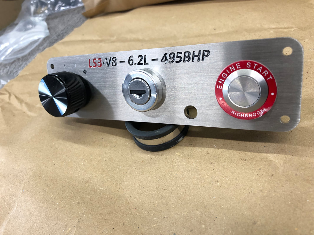
 Dashboard Switch PanelsFor ages I have been pondering how to mount the switches and tell-tales onto the dashboard. In particular the tell-tales only have a small collar, which means it may be difficult to make it look right if the hole is slightly too big or too small. Therefor I decided to design some brushed stainless steel mounting panels. A company called 'Lewis Howes Signs & Engraving' did a brilliant job creating the panels according to my design for a reasonable price.
I am really pleased with the end result and they will look amazing.
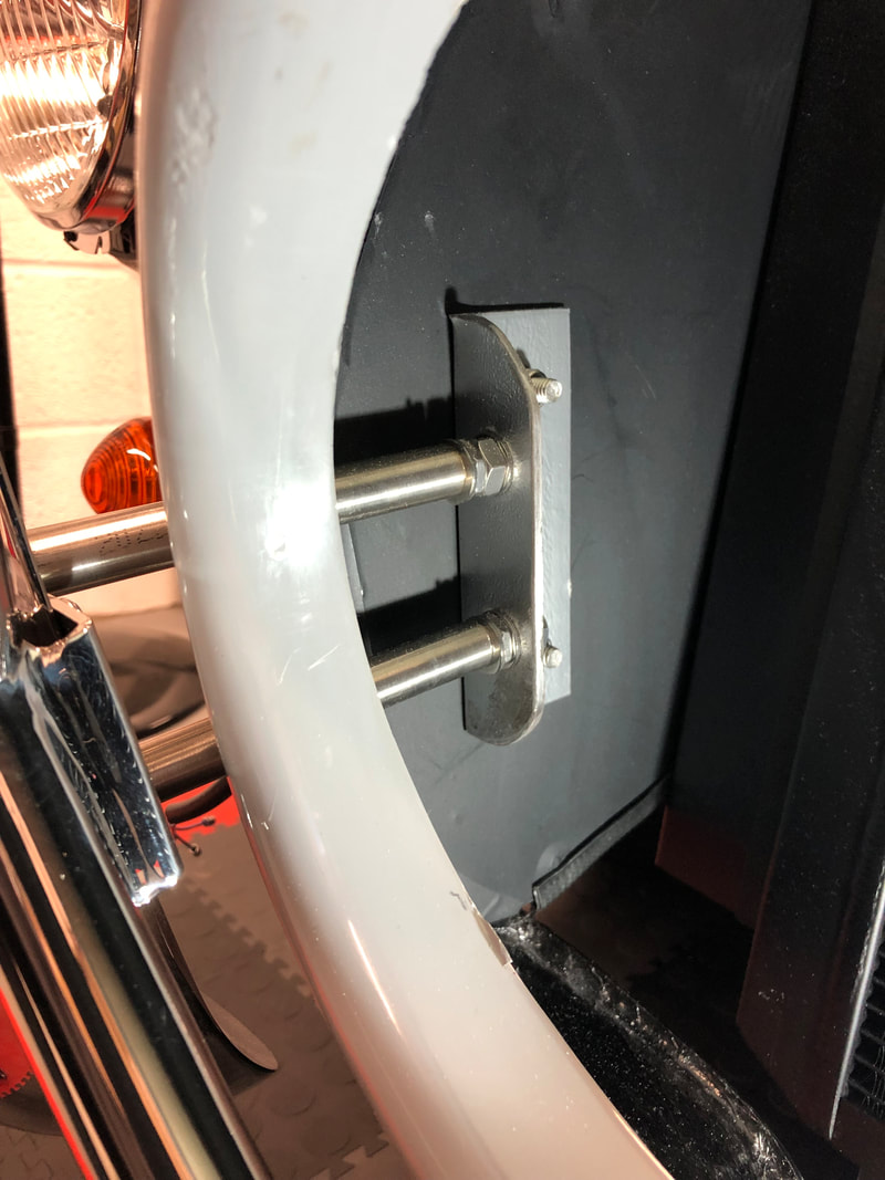
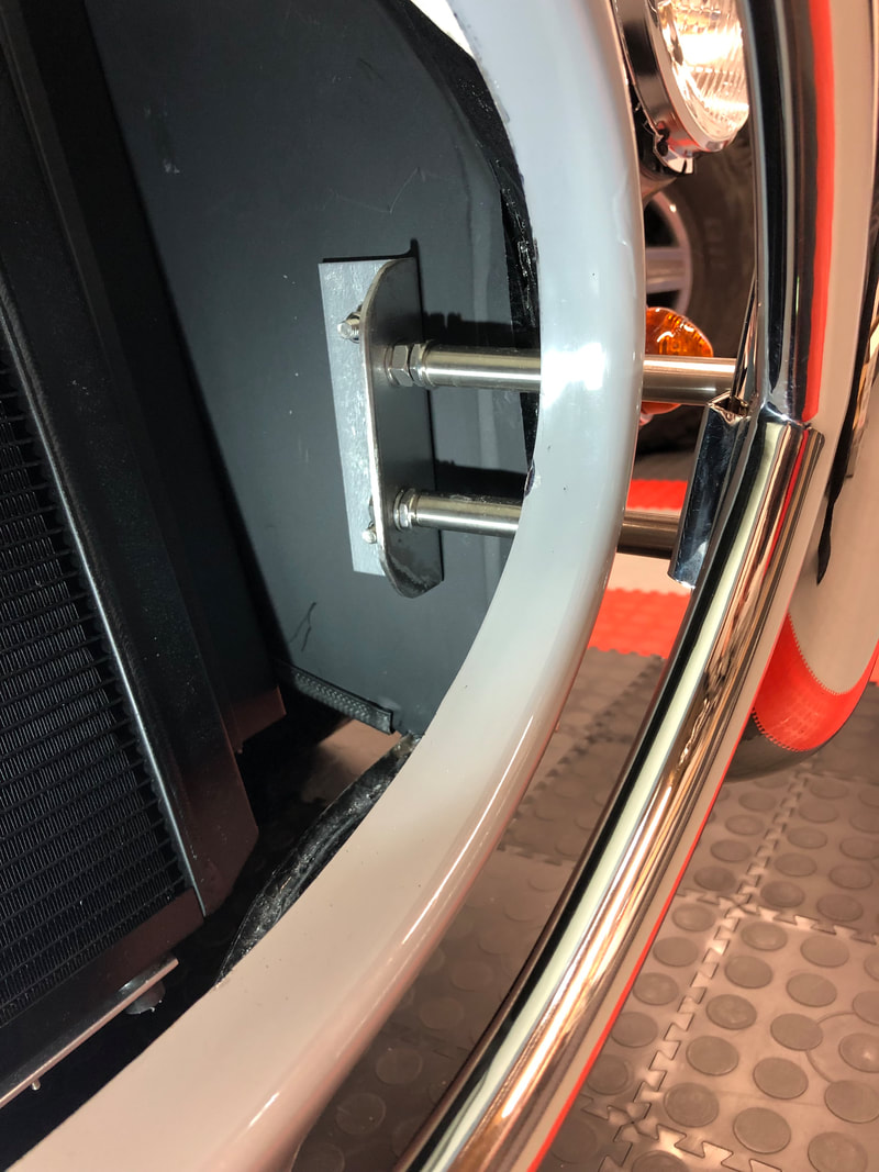
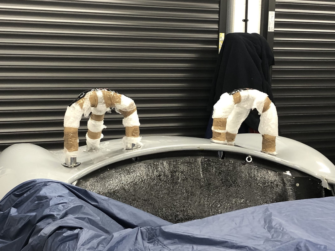
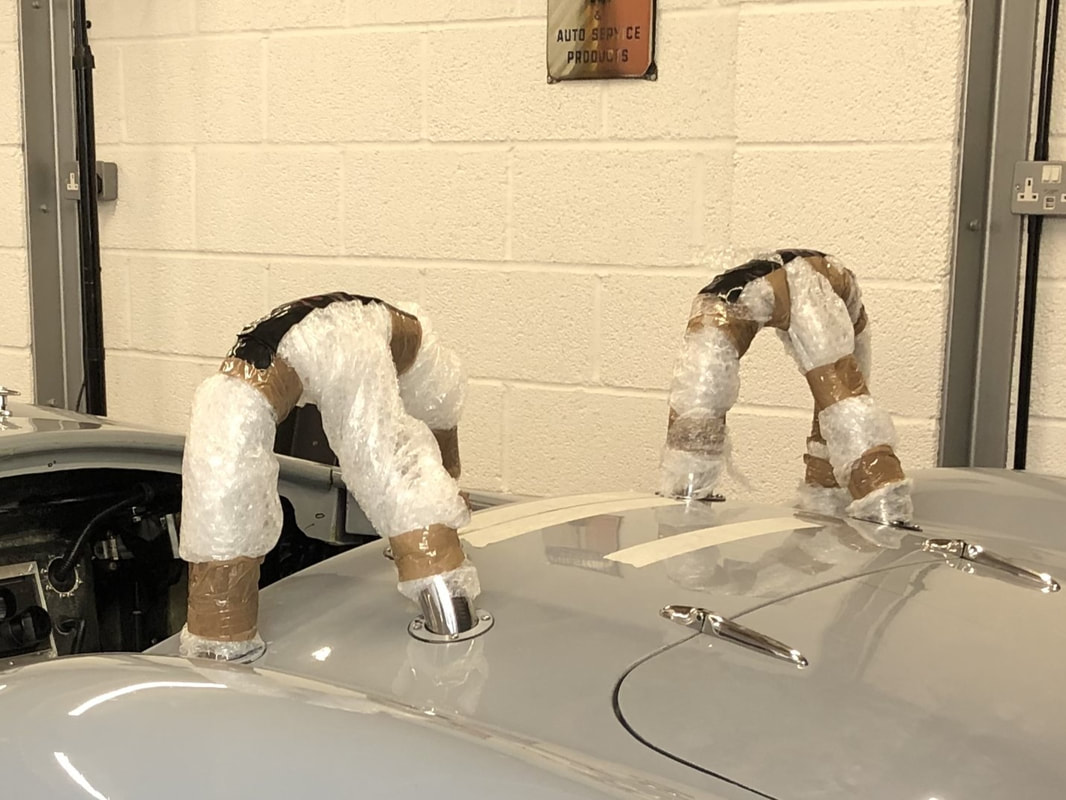
Rear Nudge BarAs with the front nudge bar, I have no intention to run with these as I prefer the look with quickjacks. However, I want to make sure that the holes in the body allow these to be interchangeable so myself or any potential future owner has the choice to run with either. To mount the nudge bar in the correct position, I started by marking a centreline on the car body. This was easier said than done as nothing is symmetrical, in particular the recess for the number plate light is an odd shape and is not in the centre of the bootlid. Anyway, after several measurements I was happy with the centreline. Next I ensured that the chassis and the bottom shut line of the boot were level (having a ramp makes this very easy). I found that having the upper mounting for the nudgebar in-line with the shut line of the bootlid provided the correct height for the nudgebar. Measuring the distance from the centreline then provided the correct location for mounting holes which were drilled all the way through into the bracket that is bonded into the body by AK.     Boot Hinge ReinforcementsWhen opening and closing the bootlid, I noticed slight flexing of the rear panel where the boot hinges are mounted. As this is only single layer fibreglass, I decided to strengthen the area by bonding aluminium plates to the bottom.  The provide maximum adhesion, I drilled the plates with holes with holes and then used P40 to bond it to the inside.  Front Nudge BarOne of the big decisions for Cobra owners is whether to go for a more racing look and fit 'quick jacks' as per the original race cars, or whether to go for the road car look and fit nudge bars. Although I am leaning towards the camp of going for the race car look and fit 'quick jacks', I want to make sure the mounting locations are compatible with nudge bars too in case myself or a future want to change the look of the car. As Brasscraft no longer do produce 'quick jacks' and nudge bars, I was informed that Anthony Hale from Absolute Horsepower sells a set of high quality 'quick jacks'. After placing an order and speaking to Anthony, he confirmed that the distance between the two holes of the quick jacks is 2 1/4 inch. Shopping around for nudge bars that have 2 1/4 inch distance between the centre of the mountings on each side proved unsuccessful (Carbuilder Solutions used to advertise them, but they stopped supplying them). After speaking to Anthony again, he confirmed that he never had any issues swapping nudge bars for quick jacks, so I was happy to place an order with Europa Spares for a set IVA compatible nudge bars which arrived a few days afterwards. Interestingly, the treaded holes in the front over riders are 2 1/4 inch apart which matches the 'quick jacks' (for some reason the treaded holes in rear over riders are 2 1/2 inch apart). I used two pieces of wood measuring 2cmx2cm to align the nudge bar with opening at the front of the car and to ensure a even gap.  To find the correct location for the holes in the body, I inserted some short (8cm) threaded bar in the over riders and secured it with a locknut. M8 treaded bushes allowed me to extend it to the point where it touched on the fibreglass body.  There is no straight forward reference on how to align the nudge bar with the body, in particular as the lower lip in the opening on the body does not seem to be perfectly symmetrical. For this reason I decided to keep an even gap with the oil cooler opening and made sure the left an right corner of the nudge bar had a similar overlap. 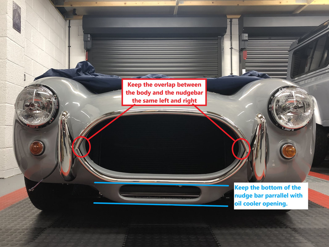 a With the nudge bar in the correct location, I marked where the treaded bushes touched and drilled an 8mm holes. After several iterations of offering the nudge bar up to the body and gently opening each of the holes, I finally got to a position where the bars would fit through the body. AK Sportscars supply two brackets that need to be fitted to inside of the inner wheel arch. Although the brackets have 9mm holes to mount it to the wheel arch, there is no specific location where these should be mounted, so I took an educated guess. I decided to cut the treaded bar into 17.5cm long sections, which I mounted to protrude from the overriders by 15cm. The stainless steel tube that covers the treaded was cut down to 12,5cm sections, leaving 2.5cm for the bracket and the nut on the other end. The brackets that AK provided are 140mm tall, so I marked 1 1/8inch from the centre of the bracket. The distance from the treaded bar to the inner wheel arch is not exact and depends on where AK happen to bond the inner wheel arch to the body. When offering the bracket up to the inner wheel arch, I measured anything from 18mm to 25mm, so I drilled the holes in the corresponding locations. Finally I decided that the square L-shaped brackets from AK looked a bit agricultural and overkill, so I decided to trim any excess metal and rounded some of the edges. At a later date (when I have a batch of parts) I will get these re-powder coated in matt black.
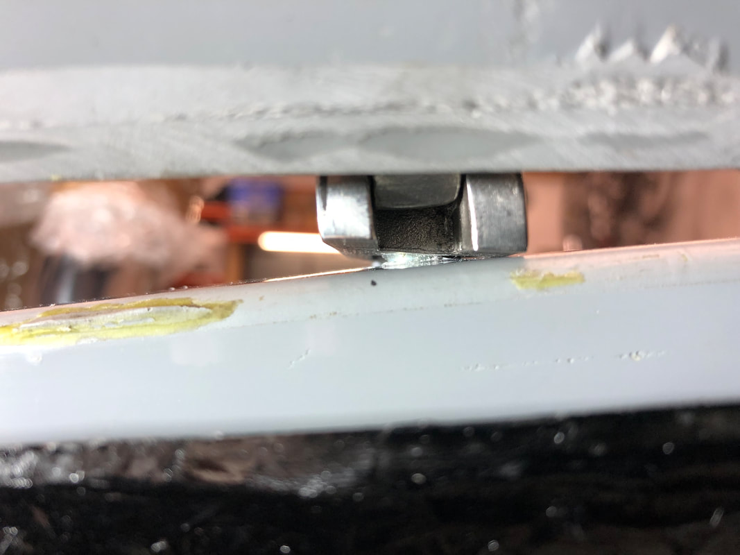
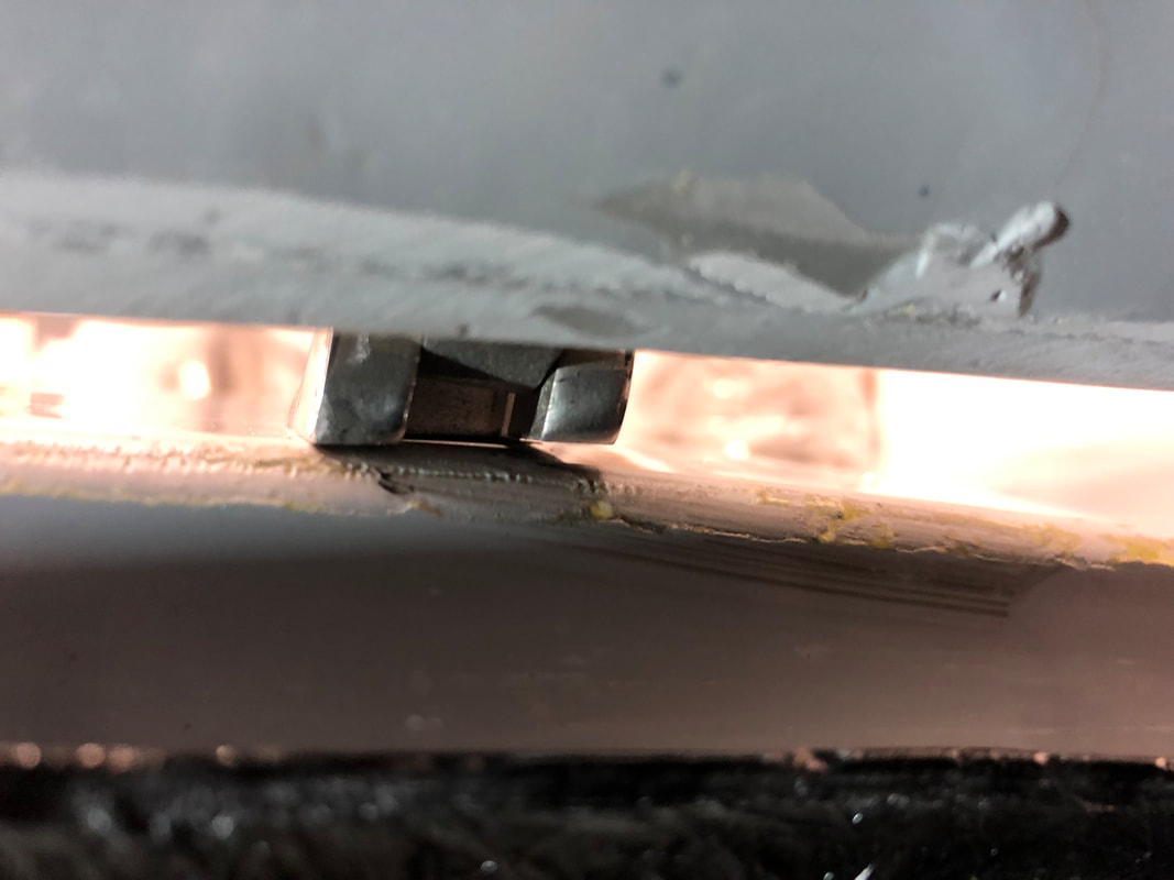
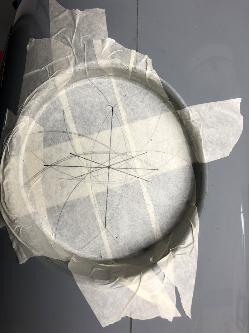
Boot HingesTo make sure both hinges are aligned and square, I made a template with the measurements of the boltholes for the hinges, the hinge pin and the vehicle centre line.  To determine the centre line of the vehicle, I marked the centre between the front inner legs of the roll-hoops and the centre between the third legs of the roll-hoops. Before sticking the template down, I positioned the boot lid ensuring equal gaps all the way around and fixed it in place with tape. I then positioned the template to align the centre line and hinge pin line with the ones of the vehicle. 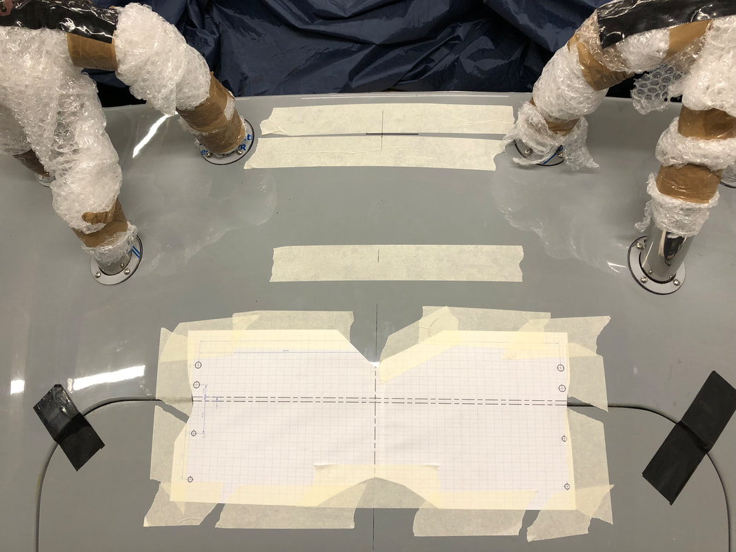 Using the centre marking for the holes on the template, I drilled small 3mm holes which I gently increased to the required diameter. Somewhere in the internet I read that you need to be sure the hinges are installed correctly as they are handed. At the time, I thought 'obviously, the shorter thicker end goes to the front and the longer thinner end goes to the back'. However, after mounting the hinges, I noticed that the hinges started to bind once I tried opening the boot lid more than 1/4 of the way. When looking at the hinges while the boot lid was partly opened, I noticed these were not sitting square on the body. It then dawned on my that the comment I read on the internet and flippantly dismissed, was in fact true and the hinge pins are angled to account for the curvature of the body. Swapping the left and righthand hinges quickly fixed the issue.
However, even with the hinges the correct way around there is some minor flexing in the body when the boot lid is being opened or closed. As there is no real re-enforcement in the area, I will bond an aluminium plate to the inside in the near future to strengthen the area and avoid the paint from cracking.
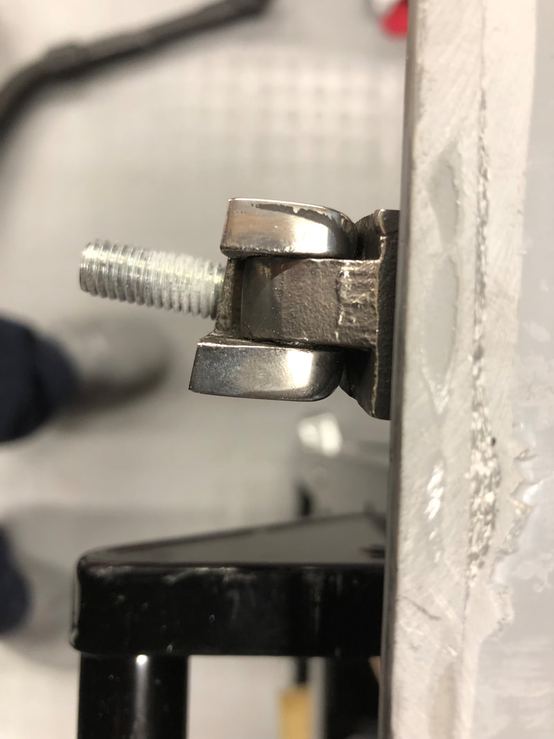
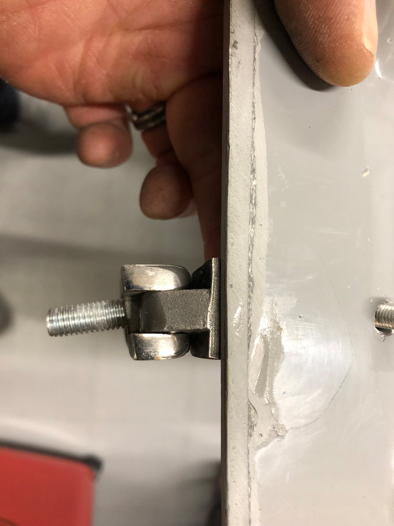
Roll HoopsAfter fitting the body onto the chassis for the final time, it is possible to fit the roll-hoop brackets which also clamps the fibreglass body down. I noticed there was some thick powder coat / paint on the inside of the brackets where roll-hoops fit into. As I wasn't sure how tight the roll-hoops would fit in the brackets, I decided to remove any excess paint with a Dremmel and coat the inside copper grease. Secondly, there is no means of securing the roll-hoops, so they could either work their way upwards and get lose, cause an annoying rattle or someone could just pull them out. To stop any of this, I decided to secure the roll-hops into the brackets with grub-screws.  The holes in the body to fit the roll-hoop through are pre-cut by AK Sportscars in the factory. However, the cutout for the third leg on the near-side did not line up with mark that was made in the factory prior to cutting the hole. When I offered the relevant roll-hoop up to the body, the third leg appeared to be more aligned with the mark rather than the hole in the body. I will fit escutcheons anyway which will cover any gaps, so I decided to gently open up the hole until I managed to fit the roll-hoop through.
However, my worry was unfounded as once the roll-hoop was pushed through the hole, the top of hoop appeared to be closer to aligned to the original hole. All I can think is that the leg is not perfectly straight but once all are located in the brackets, it moves everything into line. In any case opening up the hole will not hurt as it will be covered by the escutcheon and it will relief any strain on the paintwork later on.
The escutcheons themselves took some fettling to get into shape, but I am happy with the final result. Seatbelt Top MountWhile fitting the roll-hoop brackets, I also made the hole for the top seatbelt anchorage.
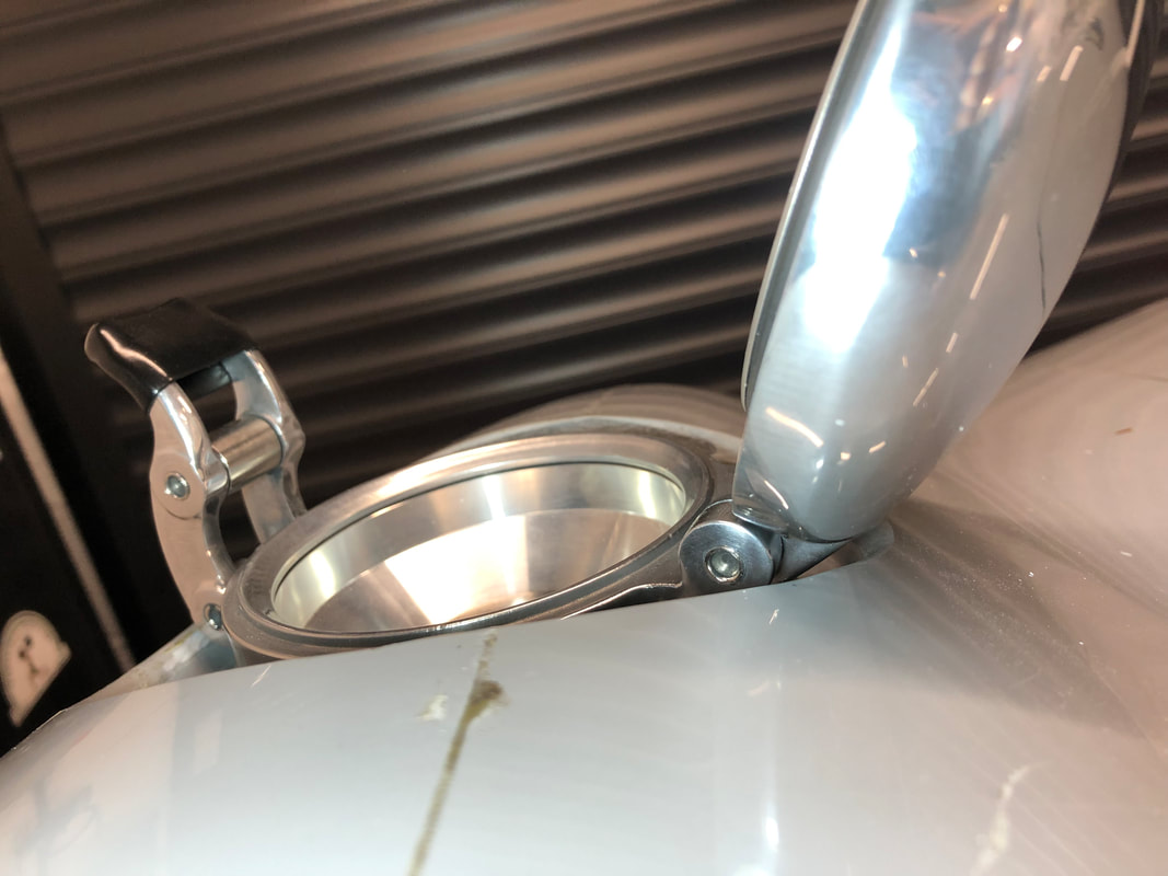
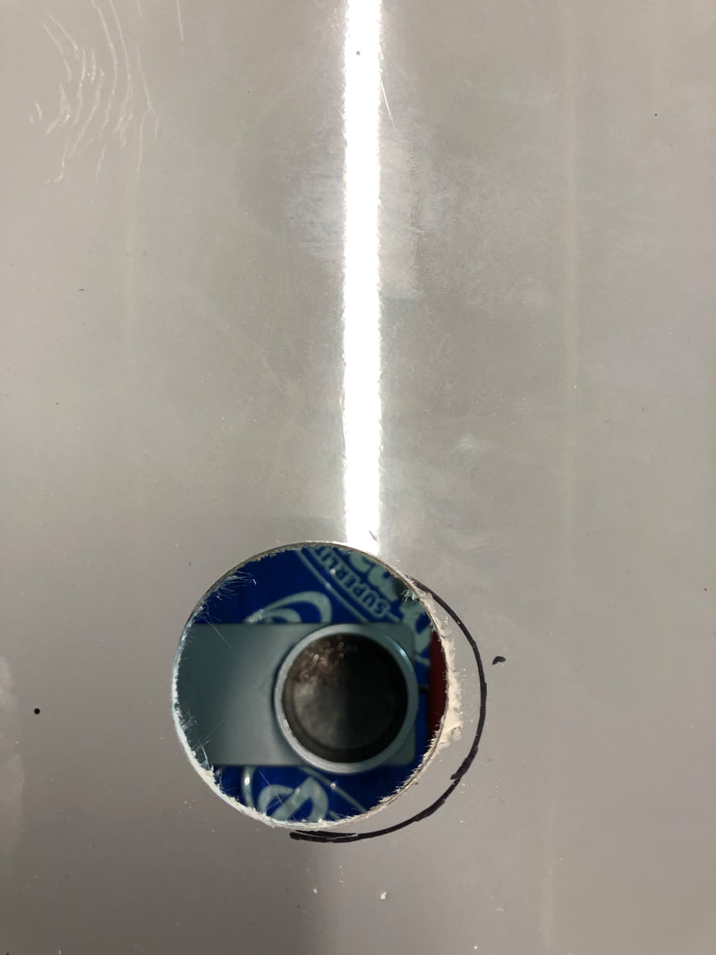
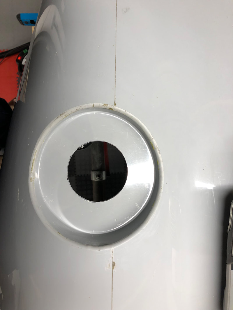
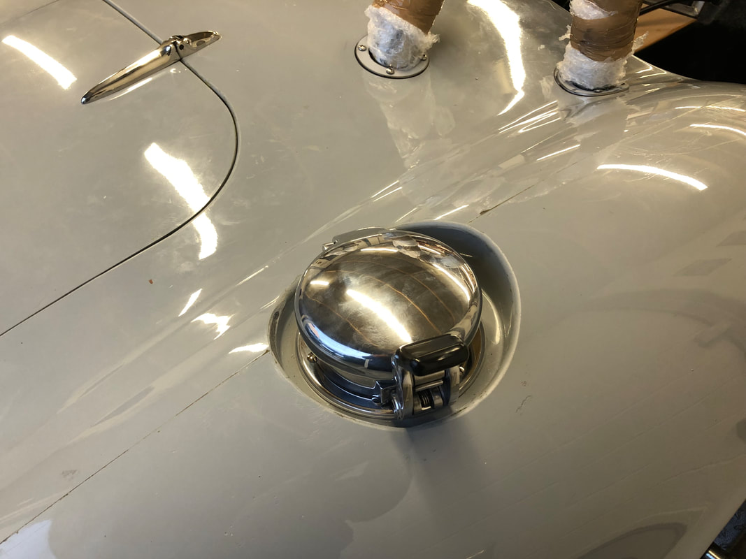
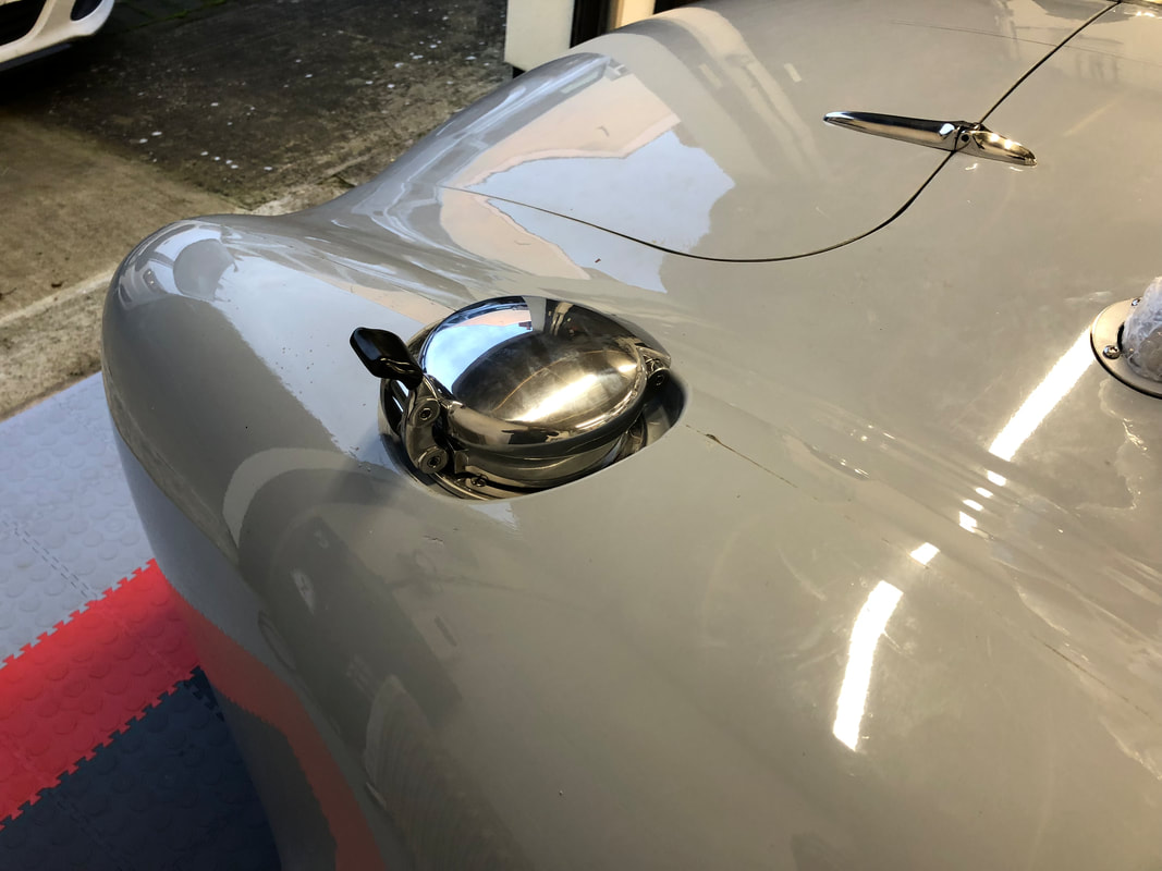
From the inside of the boot area, I drilled a small pilot hole (2.5mm) through the bulkhead on either side of the upright section of the roll-hoop bracket. This will be covered by the interior trim, so nobody will notice anyway. Using the two pilot holes as guide, I marked the underside of the lip on the rear bulkhead and drilled another pilot hole in the middle. This allowed my to fit a nail (or a rivet) through the third pilot hole and find the treaded hole in the roll-hoop bracket. The angle of the nail then provides a guide as to which direction the hole needs to be opened into. Battery cutoff switchWith the body back on the chassis, I was able to mount the battery box in its final location. As per IVA rules, it is mandatory to have a battery cuttoff switch that disconnects the battery from the car. The rules state that this also needs to have a removable key. I decided on a marine spec switch that comes with a mounting box and as capable of 220Amp continues and 1000Amp for 5 seconds. The outlet of the cutoff switch feeds two mega fuses; one 250Amp for the 'dirty feed' to the alternator and starter motor, and one 100Amp to the supply power to the cabin fusebox. 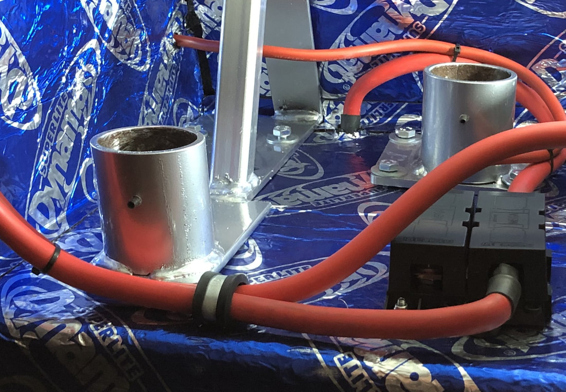 Fuel FillerI wanted to fit the fuel filler before the body is married with the chassis as it provides easier access to the inside wheel arch and it stop the suspension being covered in all the fibreglass filings. Using my trusted compass, I determined the centre of the recess for the fuel filler and used a 54mm hole saw to create the hole.
Before creating to holes that bolts the fuel filler to the body, there are a few things you need to be mind full of:
With the fuel filler in place it was time to connect the filler to the tank. I already drilled two holes in the inner wheel arch; one for the filler pipe and one for the breather hose. The 51mm joiner pipe that connects the breather pipe was sourced from Ebay. Wire clips are used to make sure a tight seal is created wit the flexible fuel filler pipe.  |
AuthorMichael De Cock Archives
April 2024
Categories |


 RSS Feed
